Striker RDF is a system for real time data acquisition, visualization and tactical planning associated with the detection and triangulation of a fixed radio signal source. In radio direction finding (RDF), a series of data collection points are surveyed at various locations over a period of time and analyzed to estimate the probable location of the signal source (i.e. the fox). Striker RDF is used for amateur radio fox hunting (RDF).
The system
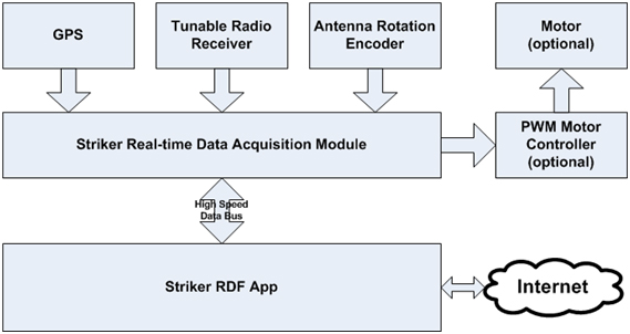
High speed data acquisition is achieved by taking many measurements very quickly while simultaneously rotating a direction antenna mounted to a vehicle that is traveling at a high rate of speed. The rotation of the antenna can be manual or automated with the use of a motor driven rotation system. Synchronized RF signal measurements are recorded many times a second which are aligned with the bearing of the antenna. The antenna bearing is determined in real time by adding the relative direction of the antenna from the vehicle to the heading the vehicle is traveling. Antenna position is gathered using an absolute rotation encoder or calculated from an incremental encoder attached directly to the antenna or motor shaft, if so equipped.
Application features
- Define hunts for each signal source discovery task
- Set start time and transmission cycle if known and then use the countdown clock to know when to listen
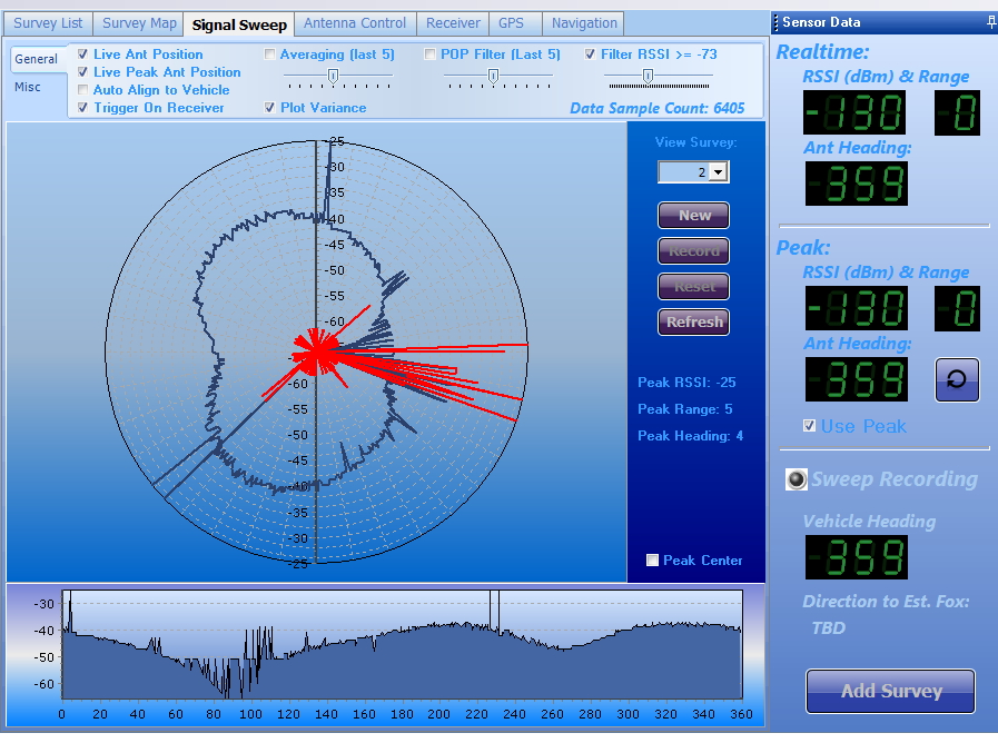
- View realtime diagnostics for antenna position, receive signal level, vehicle heading and related peak value capture
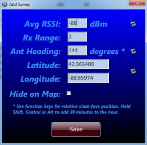
- Capture surveys on the fly while viewing antenna bearing live with peak measurement snapshots
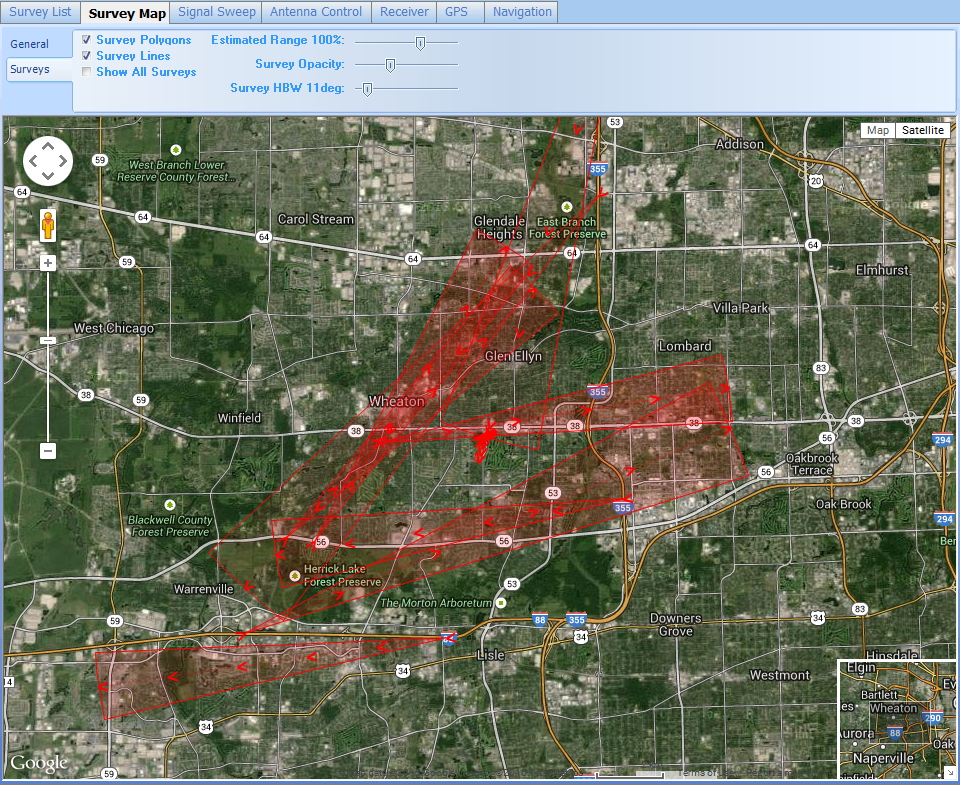
- Choose survey bearing lines or polygon representations with user controlled variable width to see probable overlap
- Record and view track log
- View estimated signal source (the fox) location and record the actual location for later study of technique
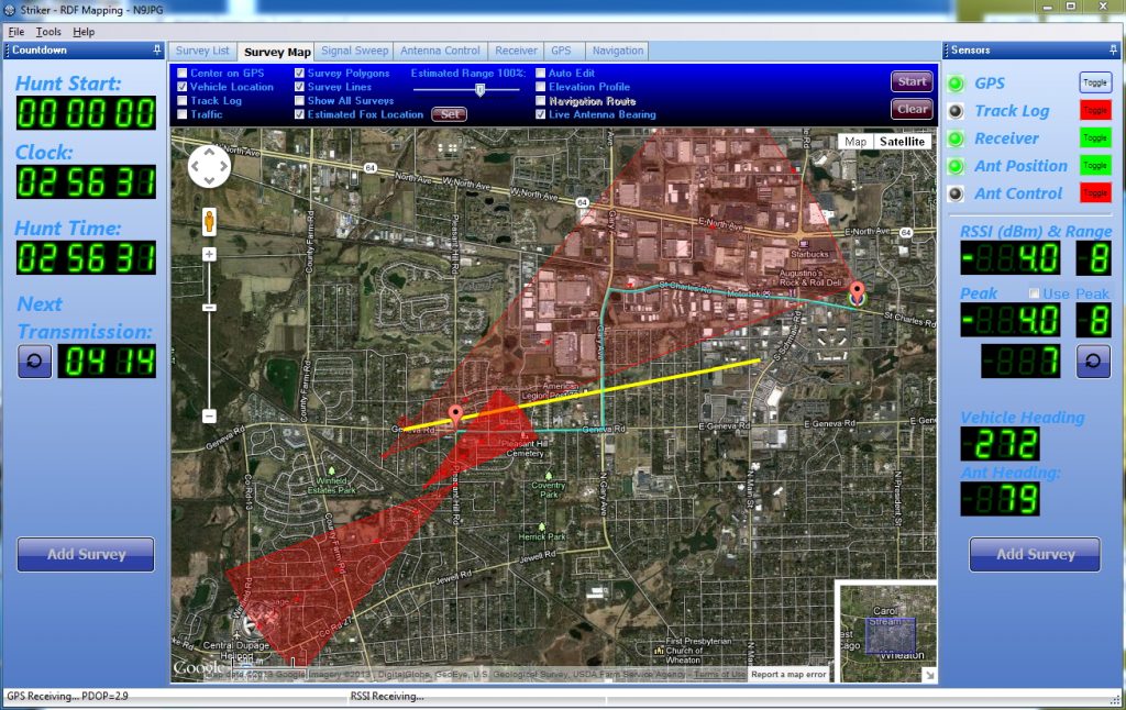
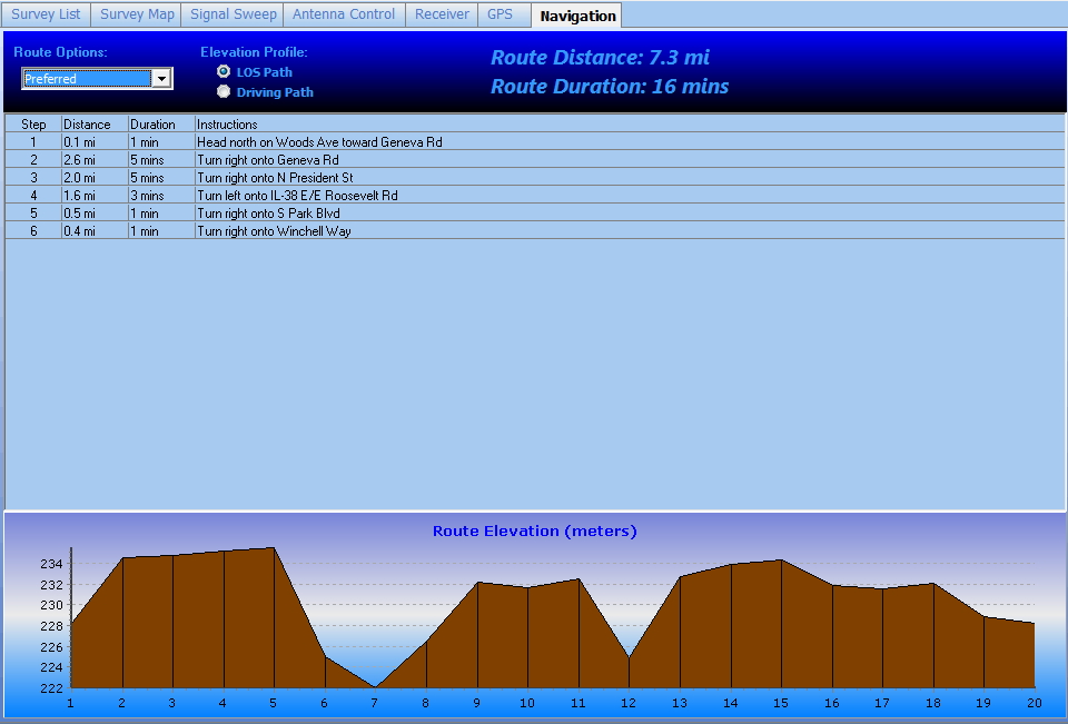
- Navigate the fastest drive route to the probably fox location with Google driving directions. Choose optimal route based on speed or highest points of altitude along the driving route for best line of sight signal surveying.
- Observe signal strength relative to true antenna bearing for each survey point location. The polar plot helps confirm the signal source direction and resolve misleading measurements due to reflections.
- Apply various numerical filters to better define the main lobe of the signal source.
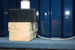
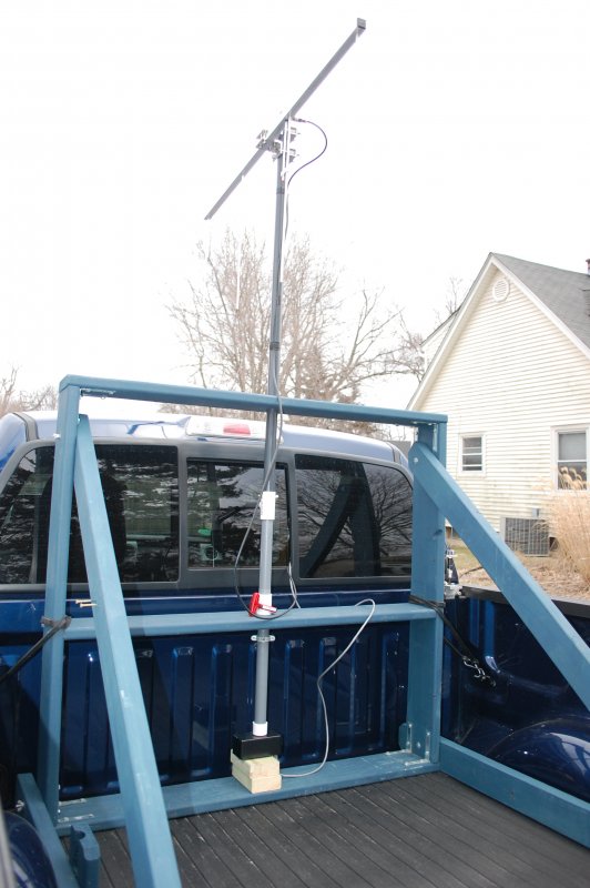
Here’s a typical antenna setup with data acquisition module in a vehicle. The antenna is turned by a passenger through an open window.
Rotary encoding using a magnetometer chip inside the sensor enclosure I built using an Arduino Uno. The white end cap had a strong magnet that is diametrically magnetized. Vibrations in the vehicle didn’t allow this to work reliably and I’ve since moved on to using rotary encoders.